|
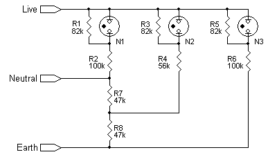
If built into a power adapter, the 230V Mains Tester is highly suitable for testing, in one safe and simple operation, that the power supplied to a device or instrument is correct. Please note that this unit is not to be used as a definitive test for a socket, and this circuit is not suitable for 120V. Although the components are likely to cost roughly that of a ready-built unit, but buying such a unit and breaking it apart often reveals a circuit board unsuitable for building into an extension cable or the like. I need to add that it's not the ultimate test (such a circuit has been known to misrepresent a fault condition), but it sure goes a long way to ensuring that power coming out of a socket or extension cable has all three wires connected!
The basis of operation is each lamp will only light if the correct voltage is present across the combination of resistors (e.g. R1 & R2 for N1). Should the voltage be too low (in the case of N1 this would be if the Neutral was disconnected), the neon will not light. R7 and R8 ensure that N2 is supplied with sufficient voltage should either L-N or L-E have full voltage, but provide sufficient voltage drop to the disconnected circuit (i.e. either L-N or L-E) such that the respective neon does not light.
IMPORTANT: The 230V mains tester cannot identify a Neutral/Earth reverse as these are both derived from the same connection at the supply. Safety is unlikely to be affected as Earths should be able to take full load current, but it is strongly advised to do an earth leakage test if there is concern. If no lights or a combination of lights illuminate when using the tester, there is a fault in the circuit which may be diagnosed with the help of the table below.
If a combination of lights do not correspond with the chart there is a more complex fault involving the mains consumer unit or other sockets wired into the circuit.
© 29.10.03 |
 MEASUREMENT TECHNIQUES: