|
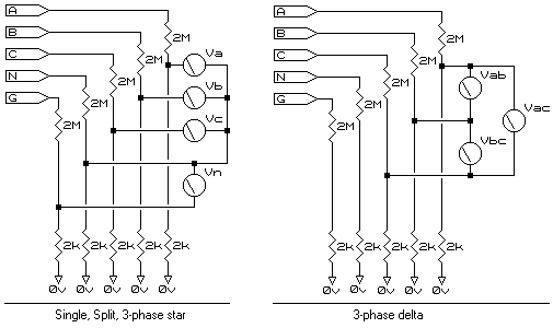
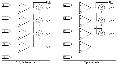
"Understanding the input structure Each input in the Reliable Power Meters' Power Recorder or Multipoint is a 1000:1 attenuator terminated on the unit's ground. The readings are derived as shown in the diagrams.
Except in delta mode, voltages Va, Vb, and Vc are all with respect to Neutral and Vn indicates any voltage between Neutral and Ground. Vn does not in any way affect Va, Vb, or Vc and can be used as an independent channel complete with its own event and trend graphs. The only restriction is that all signals must be commoned to Neutral. In 3-Phase Delta mode the N and G inputs are not in any way processed and may remain unconnected without the fear of upsetting readings. It is important to remember that with each attenuator terminating on the instrument's ground, any input not connected will assume the instrument's ground potential. LOW SPEED (normal capture, 0..63rd harmonic)
Although the unit is designed to indicate voltages measured Phase-Neutral (this is substantiated in the above explanation), it is actually not so. ALL readings are taken with respect to the Ground input via a typical 'balanced input amp', as shown above. Not shown (for the sake of simplicity) is the 4000Hz low-pass filters that feed the Digital to Analogue Converters which are processed by the Digital Signal Processor. The only part referred to is the processing of the signals. During the reading process (i.e. on every one of the 128 samples per cycle), the first part of the mathematics performed by the DSP is to derive the desired results from the values read by the ADCs. In single phase, split-phase, and 3-phase star ('wye'), each phase is subtracted from the Neutral-Ground to give the desired reading of Phase-Neutral. In 3-phase delta, the summation is performed across the phases as required to derive the desired phase-phase readings. In all of the above, the maximum readings are limited to ±1000Vpk. This is specifically important in the 3-phase delta mode as this limits the phase-phase (line-line) input to 1000Vpk (707Vrms). This is a limitation of the DSP and not the electronics. If higher than this voltage needs to be read, then either use 3-phase star which will allow a maximum of 1225Vrms phase-phase, or use resistors to extend the input range (see here). The Phase Locked Loop (PLL) of the unit also operates, as per the rest of the electronics, Phase-Ground, except it is always PhaseA-Ground (this cannot be switched). There must be a Phase-Ground voltage for the phase lock to be effective (and about 12V and up is required). The PLL is particularly affected with readings taken on domestic supplies with Live and Neutral reversed, or with a floating system if Live has a superb Ground fault. Careful investigation of the initial scope readings, by 'positive summating' the Va and Vn values, it can be seen what voltage is present on PhaseA-Ground and show whether there is sufficient input for the PLL. If too low, the frequency trends tend to error ("flat-line") at a prescribed maximum. Definition: The power taken from the test points by the inputs of an instrument. Technical submissions often ask for the 'burden' a specified power recorder will place on interfacing VTs and CTs. The Reliable Power Meters' range of recorders is listed below in the two categories of voltage and current. Voltage This could be less if the 110V is found line-line (63VACrms to Ground). In this event the burden could be as low as 2mW. However, it is best to state 6mW as maximum possible load in the event the recorder is connecting to a system with a grounded leg. Current
The MultiPoint internal CT input impedance has been measured at 10mW contact-to-contact. With P=I²R, this makes the burden 10mW at 1A, and 250mW at 5A.
If there are any questions please email Note: This web page does not form part of any official documentation. © M.T.P. - 05.11.03 |
|||||||||||||||||||||||||||||||||||||||||||||||||||||||||||||

