|
Safety first...... When measuring mains supply voltages up to 1kV it is recommended that test leads comply with GS38 and are 1000Vrms CAT III certified. There is often the requirement to have an instrument, in our case an electrical power quality recorder, work just outside the input range. Resistors offer a convenient way of accomplishing this thus dispensing with having to resort to costly voltage transformers. There are two main methods of using resistors to reduce the input voltage into an instrument being either voltage dividers or in-line voltage reducers (a form of voltage divider except that one portion of the divider is the instrument itself). The deciding factor as to which method is used is the voltage being measured and the upper limit of the insulation. As a guideline the voltage being measured should not exceed 1kV (ok, 1.1kV as this is a standard voltage) as the test leads may flash over. If measuring beyond 1kV then a fixed voltage divider is called for and is discussed separately. A standard input for a power quality recorder is likely to be a voltage divider (with a loading of 1kΩ per volt or better) that reduces the input voltage to what the analogue-to-digital converters can process (usually no more than a few volts). There is usually a limit to the input voltage too, mainly imposed because of safety, and 1000V is not uncommon. 707Vrms is also very common with 707 * 1.414 = 1000V peak. Increasing the input capability of an instrument by a few hundred volts is easily accomplished by popping a resistor in line with each input thus effectively increasing the voltage divider ratio. The only rule to obey is safety ensuring the voltage being measured does not exceed the test lead insulation voltage, and the voltage across the extra resistors does not exceed the breakdown voltage of these resistors. In our example we required that our recorder measure a maximum of about 850Vrms (1200Vpeak). We settled for a simple multiplication factor of 1.5 thus raising the peak to 1500V thus giving a little headroom for swells and surges. One must also note that any trigger voltages are also increased by the ratio added into the input divider.
To calculate the extra resistance the loading of the instrument is required. Once known the extra is determined by |
| Rx = Rin(DV / Vfsd) |
|
where: The Reliable Power Meters' Power Recorder is 2meg input. We want to extend the peak input by 500V on top of the available peak input of 1000V (as this allows a simple voltage multiplication setting of 1.5). With our formula we calculate the required in-line resistance to be 2(500/1000) = 1meg (yes, this was deliberate!).
One other thing to remember, when the lead is disconnected from the instrument the full voltage of the point being measured is now available at the end of the test lead. It is highly advised that the instrument be fully connected before attaching the test leads to the test points.
© 19.07.01 |
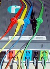
 Caddock high voltage resistors, fitted with caps from old fuses (as shown alongside), replace the fuses in a set of fused test leads. The leads are used in 'reverse' with the fuse holders closest to the instrument (as shown in the main picture). This minimises the lead length that may pick up extraneous noise and add to the harmonic readings.
 Fused croc-clips, such as those available from