|
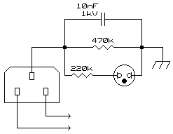
LEGAL NOTICE: The following modification will force some instrumentation to no longer comply with certain Health and Safety requirements. You use this circuit at your own risk. It is strongly suggested that should you do this modification to any instrument you clearly mark it in such a way that no ambiguity exists and also, when being used, the instrument be shown to be live. It is often required that an instrument not be strapped to earth via the mains connector, be it that earth loops are created when testing within a circuit, or that the device under test has a chassis potential away from earth and could result in damage should earth be connected to it. A prime example of the latter is a TV set. When testing such equipment it is often desired that the instrument not be earthed but when not in use the chassis of the instrument be at least at earth potential. Many times, too, having a soldering iron "hard earthed" can result in damages to equipment being repaired but disconnecting the earth can result in the tip "floating" at approx. 125VAC (half way between 0 and 250VAC) due to capacitive coupling between the element and the casing, this possibly leading to damage of very sensitive equipment being worked on. In both cases it is then desirable to "soft earth" the instrument or appliance. This is done with a typical circuit shown below. This circuit is usually no more than a 470 kilo-ohm resistor and a 10nF/1kV capacitor in parallel, this combination then placed in series with the earth lead. The circuit below has, however, a further resistor and neon lamp shown. This serves as an indication that the chassis is at an unsafe potential and to be treated with the utmost of respect!
If there are any questions please ask before implementing this circuit.
© 14.08.00 |
