|
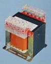
NOTICE: Voltage levels mentioned in this article are lethal. Installation of this type of equipment is to be carried out by qualified personnel only. Note to Qualified Personnel: Please ensure the Neutral connection of such an auto-transformer is secure and free of any interruption as if allowed to float the full line potential of 660VAC will appear at the measuring instrument and could endanger life. Please do not forget the fuse in the live side, fuses have a very real and valid purpose. Mains voltage measuring instruments are usually designed for household levels (115 or 230VAC) whereas industrial levels are often 660VAC 3-phase supplies. Measuring voltages at this level has two challenges, insolation breakdown and instrument overrange. A simple auto-transformer arrangement offers a solution to both the above mentioned headaches by reducing the voltage to a level at which the instrument is both safe and capable of reading. An isolation transformer is the desired solution as these are usually designed with very high breakdown voltages (remember, the peak voltage of a 660V input system is 660 * 1.414 = 933V). A preferred transformer is a 240 input to 2 * 240 output but these are, however, rare. More commonly available is a 400 to 240 volt type catering for 380V 3-phase delta installations (no neutral). These are usually supplied with a number of tap points, our example shows 400/415/440. The trick comes in chosing and wiring the transformer properly. Unless loaded properly large transformers are susceptable to phase shift. Experimentation has shown small 20-50VA types very suitable for this type of work. The usual low impedance of the supply counteracts the residual magnetism of the transformer so any sudden disturbances (1/4 or 1/2 cycle dips or swells) will appear at the output. As shown in the diagram below the 240V output point is used as the low voltage end of the 660V input end, this creating the auto-transformer.
Testing to ensure the phasing of the two windings are correct should be conducted at low and safe potentials. This should comprise of 12VAC injected into the output side (i.e. across the Neutral and 238V Out points) and, if all is well, 33VAC should be measured across the 660V IN and Neutral. If this is not achieved swap the polarity of one winding only. If this test is successful only then should this circuit be implemented at full potential. Should measurements of 3 phases be required 3 such transformers need to be employed, please note that they should be mounted with at least 25mm (1 inch) seperation to ensure no cross magnetisation occurs which could affect readings. A suitable transformer is available from RS Components, Cat. No. 180-190. The transformer features a 400/415/440 input with a 240 output, the 415V tap is suggested as this offers a very workable ratio of nearly 2.75:1 (660V:240V). This transformer also features some desirable characteristics especially with regard to insulation (as copied off their website).
© 15.03.01 |