|
This one stumps even some of the most advanced RF engineers, that is, the "gain" of an antenna. Even the law states that the "Effective Radiated Power (ERP) will not exceed..." and this is based on the input into the antenna multiplied by the antenna gain. There is this concept that, the moment they exhibit gain, antennas magically create power within themselves. Sadly, this is not the case. If one examines an antenna it will be noted it is constructed of basic materials, the best being gold, silver, copper, then aluminium following on. These materials in themselves cannot create power. Before we go into any explanations there are some terms that need definition so-as to assist in the explanation of antenna gain. decibel (dB): unit of measure of loss or gain. Gain has a positive value, loss has a negative value, and is equal to 10*log(Pout/Pin) Antenna Gain: The relative increase in radiation at the maximum point expressed as a value in dB above a standard, in this case the basic antenna, a ½-wavelength dipole (as in Two-Poles) by which all other antennas are measured. The reference is known as 0dBD (zero decibel referenced to dipole). An antenna with the effective radiated power of twice the input power would therefore have a gain of 10*log(2/1) = 3dBD. A note of warning: There is a second 'reference' used in antenna gain figures but is used to simply give an antenna a higher gain figure than what is truly achieved. It is known as dBi and represents the gain of an antenna with respect to an imaginary isotropic antenna - one that radiates equally in a spherical pattern (equal in all directions). It increases the antenna gain figure by 2.14dB, this being the 'gain' of a dipole over an isotropic antenna; But this is not a head start! This is covered more in the paper "Cheating with Antenna Gain"
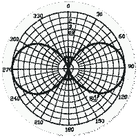
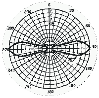
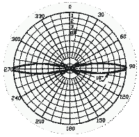
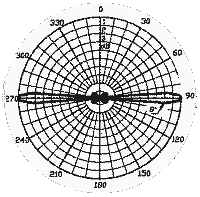
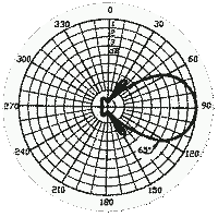
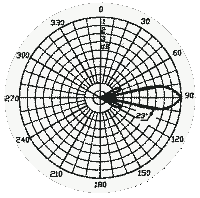
All radiation patterns on this page are with the antenna element(s) mounted vertically, and viewed from the side (i.e. right-angles to the antenna) as seen alongside. Radiation Angle: It has been generally accepted that beamwidth is the angle between the two points (on the same plane) at which the radiation falls to "half power" i.e. 3dB below the point of maximum radiation. Using anything other than 3dB does not do an antenna's reputation any good as this could give the impression the antenna has a wider/narrower beamwidth and if a serious engineer looks at this he would, rightly so, discredit the design. Coverage: The physical geological area where signal is still at a level which can be received, usually described as a radius distance from the antenna site.
This focusing can be even further intensified such that gains of 6dB (4 times) to 9dB (8 times) can be achieved. The resultant two patterns shown below.
As can be seen the method by which an antenna is made to have "gain" is merely to focus the radiation (i.e. taking the doughnut and flattening it into a pancake) thus intensifying the radiation along the horizontal. Antennas with omni-directional radiation and gains of beyond 9dB are impractical owing to the fact that the focusing is directly related to the length (in wavelengths) of the antenna. There is, however, one further method of focusing, to now intensify the radiation in only one direction.
With directional antennas, there is one further figure to bear in mind. Front-Back Ratio: The driven element of most directional antennas is a dipole with the classic "doughnut" shape radiation pattern perpendicular to its axis. The idea, as shown, is to take this doughnut radiation pattern and squeeze it in to a beam off the front of the antenna. The reflector is usually just a single rod, maybe a collection of them. Even if a bunch, the reflector is not going to stop every scrap of energy from escaping between the cracks! Some will be radiated towards the rear (or, in the case of reception, bypass the reflector and be intercepted by the dipole). Remember, when in free space the dipole is just as sensitive to this direction as it is to the front of the antenna, and has a natural tendency to want to continue with the doughnut pattern. Even a solid sheet of metal as a reflector will not completely isolate the front from the rear because of "diffraction". Yip, the very tips of the metal will cause some signal to "bend" on the edges of the reflector and toward the rear (or, in the case of reception, from the rear toward the dipole). The ratio of this front-rear difference is defined with reference to the front (wanted) direction of the antenna, and is usually expressed in dB.
As can be seen, "gain" is also "loss". The higher the gain of an antenna the smaller the effective angle of use. This is the part people forget i.e. that they have robbed power from other directions and superimposed it on the radiation in the intended direction. This directly impacts the choice of the antenna for a specific function. Choosing the correct antenna is dealt with in "Choosing the correct antenna".
© 07.07.01 / 03.02.05 |
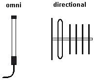 Radiation Pattern: A graphical representation of the intensity of the radiation vs. the angle from the perpendicular. The graph is usually circular, the intensity indicated by the distance from the centre based in the corresponding angle.