|
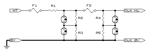
Warning: This is not for the feint hearted. Voltages spoken of here are lethal and work must not be attempted by non-qualified personnel. Using this circuit is done so at your risk. In plain English, I take no responsibility for your lack of training, experience, and/or common sense! Note: This circuit has been modified since first published as there were callings to monitor up to 6.6kV. The problem with the original circuit was the output voltage had to remain low (no greater than 220VAC) and would mean high attenuation ratios for working at 6.6kV. This attenuation can cause some loss of accuracy of harmonic data. The previous version is still available and you are welcome to view it here. There are many times voltages of beyond 1kV need to be measured, but doing so safely requires a little engineering. Most times voltage transformers are employed (see Measuring beyond 230VAC) but there are times this is not practical, especially if VTs are not available at the voltages required, or simply prohibitively expensive. A voltage divider is an apparent answer, and there is no apparent reason it shouldn't work. Imagine, however, you calculate your voltage divider, pop in a few resistors, and every seems to be going well...... and the lights go out! Now all would be well if this was your own home and all you've blown is the main incoming fuse. But you've not done this at home. You were trying to measure a major multi-kV line at the main plant where you work and now the whole plant is dead! So, let's teach you what the books didn't. Resistors have a breakdown voltage which is when the voltage between the windings exceeds the insulation between the windings. Even carbon and metal film are 'wound' on the former, the spiral shape created when the resistor is trimmed onto value during manufacture. Typical operating voltages of most commonly available resistors, which is both the voltage that may be across the resistor as well as between the resistor and its immediate surroundings, usually falls in the range of 250 to 500VAC for 250mW and up. It is strongly advised that this be checked before using any type in high voltage applications. There is effectively two issues to overcome:
We will deal with the issue of breakdown first as this affects how we deal with the resistors. Should a breakdown occur i.e. the primary resistor (R1) flashes over, then the fuses and gas discharge tubes come into their own. Their one and only purpose is to ensure the measured HT voltage is not presented to the instrument. The way this is done is when the voltage exceeds the firing voltage of gas arrestor pair G3-4 they start to conduct. During a breakdown a lot of current could be available, and with G3-4 conducting, then F2 will blow isolating the instrument. G1-2 will then strike ensuring that the full whack of the input voltage will not appear across F2 which is not capable of breaking such a voltage. Even though G1-2 are employed, it is recommended that 'sand-filled' safety fuses are used. G1-4 are capable of 20kA fault currents for short periods and therefore rely on a decent fault path (shown by the bold line in the diagram), please provide one! Please also note that 0V means zero volts i.e. Ground. It is not always possible (mainly due to cost) to have F1 being a fuse with a voltage rating of about twice the measured voltage. However, a suitable alternative is a very thin piece of wire stretched over about 2cm/kV measured. Other alternatives are to use resistive automotive 'sparkplug wire' which would vaporise under high current. The trigger voltage of the protection should be at least 1.5 times the maximum output voltage (especially at AC). With the top voltages of gas tubes standardised at 375 and 600V, the 375V limits the output AC voltage to 265VACrms max. However, these may be placed in series to increase the trigger voltage. This raises the maximum capability to 530VACrms. Our minimum ratio may therefore be 6600/530=12.45:1 (although no headroom has been catered for here). The only prerequisite for using gas arrestors in series is a method must be employed to ensure the voltage across each gas arrestor is kept equal until the trigger voltage is reached. In this design a series-parallel combination is used as the low end resistor to ensure the output voltage is divided equally across each pair of arrestors. There are two types of resistors that can be used to construct the divider. These can either be special high voltage resistors, or created from a chain of standard resistors. Caddock (www.caddock.com) are well known makers of high voltage resistors, although they are a little pricey. Strings of standard resistors have one advantage over using high voltage alternatives being the resistance of either leg can be accurately created (usually a problem - see later). With standard vs. high voltage, one needs to seriously weigh up the time spent building resistor chains with standard resistors costing a few pence, as opposed to simply wiring in costly high voltage ones. The question that needs to be asked is whether or not the circuit demands a high level of safety, and if so then high voltage types are the only way to go. Please note that there are special handling precautions with high voltage resistors, please adhere to them (manufacturers usually supply instructions). Calculating the resistors is fairly simple. For starters one should, for measurement purposes, not operate at lower then 1k-ohm/volt (i.e. 1meg/kV). This serves two purposes being:
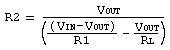
If possible (while adhering to the 1meg/1kV rule), the value of R2 should be smaller than or equal to 1-tenth the impedance of the measuring instrument. This is not extremely critical especially if the instrument can be scaled, all that is required is to calculate the loading on the voltage divider. Formulae are shown below.
If you have chosen the route of building resistor chains, then the formula for calculating the upper arm is also shown. This has the advantage of allowing you to build the exact resistance required. In our example we are measuring 6.6kV and desire the output to run about mid range of max capability (good engineering practice) of 330V (exact 20:1). Using the formula of 1meg/kV we have a lower leg of 330k. Taking this approach forces us into a position of requiring a 6.27meg upper resistor. Because of the need for this resistor to handle high voltages, it would be prudent to use more common values, and 'adjust' the lower leg of the resistor. The better route is to use the next value up (so as to not break the 1meg/kV rule) and settle for 6.8meg. This makes the lower leg 357.9k. Our instrument has an input of 2meg meaning the actual resistor we use will be, using the standard formula for resistors in parallel, 1 ÷ ((1/357.9) - (1/2000)) = 435.9k. Although such a value does not exist, one could be created using a 470k and a 5.6M or 6.8M in parallel. This will still cause a small error, but not too much to be bothered with. What must not be overlooked is we have decided to use a quad series-parallel system of resistors. What can therefore be done is that the one side (R2-3) have 5.6M, and the other (R4-5) 6.8M. The error will now be reduced to +0.2%, but experience shows that resistors tend to be a little on the low side so this is likely to be spot on! Remember, this is an example and by no means the only values you can use. One last very important figure that requires calculation is the power being dissipated in each resistor. This is calculated by working out the voltage across each resistor and then applying the formula P = V2 ÷ R where V is the voltage and R the resistance. It is strongly suggested that a safety factor of at least two be built in i.e. should the dissipated power be 250mW then ½watt resistors be employed. During construction of such a voltage divider always ensure all parts have adequate clearances for the voltages being measured. If you have chosen the route of resistor chains, it's all very well having made the chain with no more than 250V across each resistor, and then lying the circuit against a metal chassis while trying to inject 6.6kV or so (unless you like man-made lightning!). Improved Safety: This may come as a small surprise, but using this type of voltage divider improves safety. First, the voltages being taken to the instrument are now at a far safer potential than the incoming voltages. Insulation on the test leads becomes far less critical. Second, and most importantly, there are no high currents available on the test points. Should the leads, by accident, come in contact with earth (hey!, it's very easy to clamp the leads in a cabinet door), then the amount of current is limited to the input volts divided by the upper resistor value. The resistor may get a little warmer, but that is the only 'damage' done (as well as having to re-do the measurement!). For 3-phase measurements you will need to construct 3 such circuits, all using Ground as a reference point (0V). Please do not try to operate this circuit phase-to-phase as the 0V point will now be at phase potential. There are two dangers, the first being the 0V side will no longer have any current limiting, and the voltage into the instrument will more than likely be beyond the breakdown voltage of the instrument (apologies for stating the obvious, but there are those that would try this!). Please approach this with every ounce of caution you can muster, and happy measuring!
© 18.08.02 |
||||||||||||||||