|
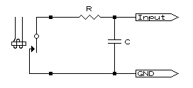
When relays are used in potential free outputs a drawback exists being the tendency to bounce on closing. If fed into counting equipment, especially fast count inputs, errors in readings result. Placing a capacitor across the input is the cure but determining the size of the capacitor is often trial and error. Knowing the input current and transition voltage a suitable capacitor value can be determined. Required are the input current, the voltage at which the input is regarded open, and the timing of the debounce. The first is determined by merely taking a multimeter, set to milliamps, and placed across the contacts of the relay. Anything from 1mA to 30 mA is the order of the day. The equipment in question had an input current of 3 mA. Determining the 'open circuit' voltage is a little more tricky. This involves using a variable resistor (20 to 50 k-ohms is usually adequate) or, if you can obtain one, a 'variable zener diode', a small electronic device deliberately designed to create an adjustable voltage drop. Place this across the relay contacts and adjust until the input is regarded as off or open circuit. Measure the voltage across the relay contacts. In our system we found the voltage to be 10v. In our scenario we required the debounce to exceed 1mS and decided to play safe and opt for 2mS. Therefor:
and using the formula C (in nF) = 667(t*I)/V we can determine the capacitor to be 667(2*3)/10 = 400nF.
In the above diagram there is a resistor shown in series with the relay contacts as the capacitor will, for a very short period, be able to deliver a very high current at every closing of the contact. This current will, after time, start to burn the contacts making them unreliable. The value of the resistor is best at R (in ohms) = 100*V/I. If we replace the symbols our scenario will be 100*10/I = 333 ohms, the closest being a 330 ohm resistor. This gives a rough guide to what is required. We only had, and therefore inserted, a 470nF in circuit and a false count was never had again. It is advised that the components be installed at the equipment end and so act as a filter against possible spikes induced on the line between the relay output and the equipment.
Some pulse outputs have a very short duration and the input may, for a number of reasons, miss the pulse. The most common reason being the input requires more time than the pulse's width to recognise the count. Don't get confused with pulse width and pulse rate. A pulse rate can be as slow as once a minute but if it is only on for 0.5ms and the input requires a minimum of 10mS on time the pulse will never be seen. If the output is a solid state (fast pulse outputs usually are) then a cure can more often than not be implemented using a resistor and capacitor. Cabling, especially long runs, is another major cause of missing counts but only in situations where the pulse is solid state driven (note, not the same as open collector) or when the pulse is from a normally closed contact. Cabling is not often thought of as a capacitor but at a minimum of 150pF/m it does not take much length to achieve a few nF. If tests can be carried out in a local environment and everything is found to be working but fails again when put on the cabling (which has been tested and found fine) then the next step should be to observe the pulse with an oscilloscope to ascertain how much the cabling is affecting the signal. Sometimes all that is required is a bit of loading on the cable (resistor) and the pulse regains it's shape. This loading may take the form of terminating the cable with it's characteristic impedance. | | Ask a Question | 24.01.01 |
 Faultfinding Count Values