|
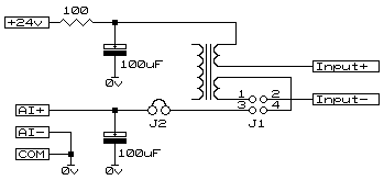
This was written after a client experienced a proportionately high amount of transmissions from a radio telemetry unit reading an analogue loop. It was found that, although the value on the input appeared fairly stable, the noise on the loop exceeded the trigger window and was thus forcing transmissions. In this instance the values were stable but other times the readings 'jumped around' and this too was attributed to the noise on the incoming analogue loop. In determining noise on an analogue input circuit a 100 ohm earpiece, as often found in telephone handsets, put in series with the loop allows noise possibly causing false readings to be heard. The source of the noise is also easily identified. In this case the loop was tied to ground on one connection which unbalanced the line to the transducer 200 metres away. Other known causes are nearby MW radio stations being rectified in the sensor electronics super-imposing audio on the loop, often not seen on meters but easily read by fast acting analogue inputs. Below is an invaluable circuit for stopping a vast proportion of such analogue loop problems, especially where balance on the loop has been disturbed. One of two styles of interference usually create the problem, seldom both together. The first (and more common) is "common mode" noise where, as in our example, the lines to the transducer are long and each picking up an equal amount of AC ripple. The second source is " differential mode" noise and usually has its origins either in the transducer electronics or as a result of one leg of the loop being a lower impedance than the other. In the circuit below there is a jumper arrangement (J1) for selecting either "common mode" (1-2 & 3-4) or "differential mode" (1-3 & 2-4) rejection. This is determined by placing the monitoring earpiece in circuit at the second jumper (J2) made available in the ground leg. This same jumper is available for test instruments eliminating the need to disconnect wires to make in circuit mesurements.
Parts for the circuit are commonly available items. The transformer a dual secondary (anything from 2x5v to 2x12v) miniature mains transformer (suggested total resistance of both windings to not exceed 100 ohms). The capacitors are suggested as 100uF at 40volts (working). Most analogue loops are powered by 24volts but should the supply be higher adjust the capacitor voltage accordingly. © 18.07.00 |
 Noise on Analogue Input loops