|
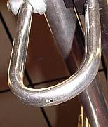
IMPORTANT NOTICE: There are situations where antennas are mounted near high voltage overhead lines. Please exercise extreme caution when erecting antennas on poles. Touching the open live conductors, even as low as 230VAC, can kill. Yagi antennas, due to there large physical size when built, often arrive in pieces and without any form of drawing or diagram by which to assemble them. To this purpose pictures showing typical 2 and 3 element Yagis are included. The "loop" is the actual antenna (dipole) with the longer of the "bars" being the "reflector" and the shorter being the "directors". Should you have a multi element with different lengths the longest is always closest to the mounting, followed by the loop, then the next longest down to the shortest at the front (in the direction of the arrow). | |||
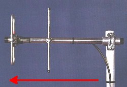 |
2 Element Yagi antenna | ||
| 3 Element Yagi antenna | 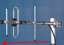 |
||
| |||
|
The orientation of the antenna (the direction in which the antenna faces) is simply from the mounting, down the antenna, and continuing on toward the system with which the station is communicating, the direction shown again by the red arrow in the pictures. Note: Polarization is of extreme importance. If the antenna at the master station is vertical, then all antennas on that system must be vertical. On one-to-one links it is sometimes chosen to operate in horizontally polarized mode, and in this case both antennas must be horizontal. Failure to do so will result in approximately 20dB loss in signal which on low power systems is ill advised. | | Ask a Question | 03.11.00 |
|||
 Assembling and Orientating