|
Resonance is very easily recognised by the distortion on the voltage waveform being a relatively uniform sinewave superimposed on the fundamental - an example shown alongside. The peak voltage is likely to rise but, as the distortion is uniformly superimposed on the fundamental, there is likely to be no increase (or very little) in the actual RMS. It is not unusual to find the trigger mechanism on some recorders to be the peak voltage (as opposed to the RMS) and will therefore trigger when the peak has exceeded a certain value. In essence these recorders are more useful for determining a bad crest factor rather than a high RMS as it is the peak voltage that can destroy electronics. However, employing such recorders may very well be a saviour with regards resonance where the RMS is not affected much. To demonstrate how to determine resonance we will use a real-life example of a major industrial site where a 33kV line was feeding a plant with huge 12-pulse motor drives. The graph shown below was drawn to simply indicate voltage divided by current, in essence the impedance, at every harmonic. This was done for a very specific reason. Resonance is indicated when the current required to produce a certain voltage at a frequency is lower than at other frequencies i.e. the impedance rises.
The evidence of the 12-pulse drives is shown as the presence of the usual 'blips' on the 11th and 13th harmonic. It's the sudden increase in the 23rd and 25th that attracted interest and the fact the voltage/current ratio of the 23rd and 25th are far different from the rest. In this case there was less than 10A of current at the 23rd and 25th harmonics, yet over 4kV of voltage at the 23rd and 25th harmonic was present on the system (as is evident on the voltage trace shown at the beginning).
Do not be misled. There is no such thing as exported or 'reflected' energy from a load. Such indications exist when the source has such a large impedance at the harmonic in question (owing to resonance) that the impedance calculations become more an indication of impedance ratio (source vs. load) rather than true impedance. Such readings are also highly possible if the load and the source are both part of the resonant circuit. The only test here is to somehow change either the load or the source 'lumped constants' (inductance or capacitance) to ascertain if there is source-load resonance.
© 03.08.02 |
 INTERPRETING THE READINGS:
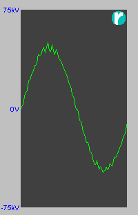 This is not something one is likely to run into on a regular basis, but when it pops up the effects are often spectacular! The first usual indicator is things getting very hot, but this is not always the case. The danger of resonance is when things don't get warm the next indicator is usually breakdown of one or other component with dire consequences - and have been known to be power factor correction capacitor banks.
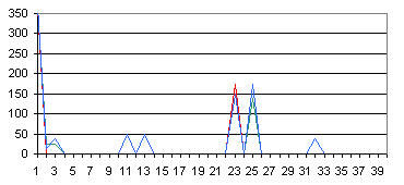
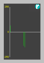 One thing not well known about resonant circuits is they want to absorb energy. In this case it is clearly displayed by impedance graphs showing the harmonic current apparently flowing from the load to the source (the load showing negative impedance).