|
...and there are no exceptions. Everything does it to some degree or another. Inrush usually happens in small doses as individual devices are turned on and results in little more than a flicker on lights. When this happens collectively things are a whole lot different. In one case an electrical engineer of a 9-floor office tower was surprised when the main incoming 250A fuses 'operated' when the system was re-powered after maintenance. The building housed a significant amount of hi-tech equipment with the average load of the complex at about 100Arms per phase. Upon examination, however, taking the rating of the fuses and dividing this by the average load of 100A shows an inrush availability (supply inrush factor) of 2.5 maximum. This means that when power was restored the average inrush allowed on all pieces of equipment, and this includes passive devices such as fridges, freezers, lamps, etc., may not exceed 2.5 times the running current before straining the fuses. A tad unrealistic, I think. This comment is substantiated when taking the inrush of something like a 17" monitor and relating this to the fuses. Each fuse was rated for 250A which means a peak current of 250 x 1.414 = 353A. Only 10 monitors could exceed this and the fuse is now strained, and this is purely the monitors without any consideration given to the other appliances mentioned above. I'm sure that many such cases as outlined above exist in peoples minds.
The typical RMS trend graph of inrush will be similar to the one alongside. The current to the left of the inrush (A) was the current of the load on the supply at the time. At the time of switch-on the maximum RMS current drawn over a half or full cycle (depending on the recorder) is shown (B). The following point on the graph (C) is the running current added to the initial load. Please do note how the maximum and average lines are used in the various calculations.
Alongside is the inrush on a 7W CFL. The peak current reached 14A, but may well be higher as the recording is limited to 10kHz via the current clamp. On a bank of lamps the peak will depend on the feed impedance of the circuit.
This inrush can be in the form of three distinct bursts, the first two happening almost simultaneously being the magnetic inrush of the transformer followed by the charging of the high voltage capacitor. The third is when the filament of the magnetron warms and the oven draws current. Some ovens keep the filament warm so the inrush on timed on-off cycles consists of triple combination of all the above mentioned inrushes.
Two aspects of the current curve are important here. The first is the serious power factor that appears as the capacitor is being charged. This is the effect of the inductance of the transformer not running at full power. The second is the prevelant curve imbalance (major peaks are only in one direction). This is as a direct result of half-wave rectification done in microwave ovens as the magnetrons operate at many kilovolts and full-wave rectification is expensive to accomplish.
Strangely enough, it is these motors that have the highest start to running current ratio and can easily exceed 50:1. In our example we have a more modern fridge with a high "energy saving" rating and comes with a relatively low start current. Our example only measured 10Arms (as opposed to peak, this being just over 14A) and, within one second, dropped to a running current of 0.7Arms - an inrush of 14:1. The worst offenders are American style (and built) fridge/freezers with motors intended for 60Hz operation being run at 50Hz. Although the start capacitor will comfortably compensate, the motor takes longer to spin up and become synchronised to the mains input and in so doing draws more current during the start phase.
If close to the zero crossing then the current is lower than at the peak. A typical computer power supply is shown alongside drawing approximately 25A peak for the first half cycle. The "blip" seen on the subsequent cycle is the fact the capacitor is not fully charged to the incoming peak voltage (owing to the current being drawn on the first cycle). During these tests, peak switch-on currents of over 80A were recorded if the switch made contact at or near the cycle peak. The damaging effect of this is clearly shown in the section "equipment failure".
This coil is wrapped around the front of the tube and fed from the mains through a Positive Temperature Coefficient Resistor. The PTCR's characteristics are a few ohms when cold but then rise to many kilo-ohms when warmed by only a few degrees. The result is a high current draw for a few cycles that then diminishes to near nothing - a perfect demagnetising method, some would say. In the accompanying screenshot it can be seen a simple 17" monitor, that usually draws 370mArms (<90W), drawing in excess of 35A at the peak of the first cycle when switched at or near the zero crossing point. This current can be as high as 40A when powered up at the cycle peak. It must be remembered that the characteristic "bo-o-ing" is also accompanied by the inrush of the SMPS that powers the rest of the monitor creating a double whammy for the mains circuit, and switch! Now there are some who like to power the monitor through the PC's power switch. This switch-on current is taken through a cable which is often lies across the motherboard.... Horror of horrors!
© 15.04.04 |
 INTERPRETING THE READINGS:
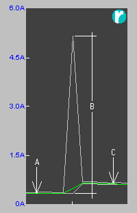 Before we show the inrush of some common items from simple through to complex, we'll show the means to identify inrush on a semi-complex recorder.
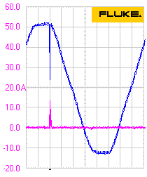 Compact Fluorescent Lamps (CFLs) are direct rectified circuits meaning a capacitor needs to be charged to full running voltage in the first cycle or two.
 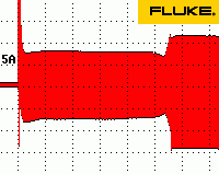 These are rather nasty devices in that the "power control" is usually a timed on-off control of the magnetron. If the oven is set to any power other than full, the inrush is not only experienced at the start of cooking but every time the magnetron is energised.
 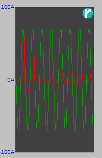 Our example was a decent high-power one (1.6kW input, 1kW output). As can be seen, the first peak is the transformer magnetising current and capacitor charge. This peaks to 56A for the first half cycle and then diminishes over the following cycles. This diminishing is typical of when there is not sufficient power transfer (high feed impedance) to charge the capacitor in the first half cycle.
 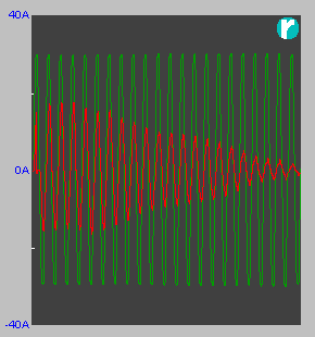 Depending on the size of the motor, start times vary enormously. Large motors usually have controllers to ensure the startup is relatively smooth and that start currents are not extortionate. However, the motors that could do with decent start circuits don't have them! Those being referred to are what are used in domestic applications; fridges, freezers, aircon units, etc.
 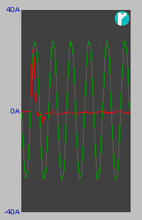 SMPSs, although they have inrush protection (in the form of a negative temperature coefficient resistor), draw an extortionate amount of current when first turned on, and very dependent where on the cycle the switch makes contact.
 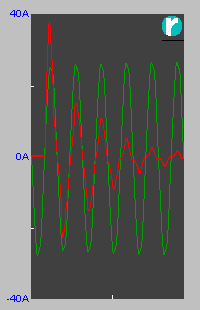 Almost all Cathode Ray Tube based colour computer monitors and television sets have coils that are briefly fed with mains voltage at switch on as a means to demagnetise the mask within the tube. This keeps the picture colour purity which could otherwise become "blotchy".