|
I was rather stunned when presented with a recording of a house and the PQ investigator announcing how "good" the supply looked. When asking on what he based this he was left with little more than a mouth full of teeth. It had been 'taught' that "this is what a good supply looked like". How preposterous! Apart from the fact that a lack of transients, surges, sags, etc. indicates a 'good' supply, ensuring the voltage remains fairly constant with varying load is probably, in the client's eyes (especially as 'flicker' will be a measure), the most important factor determining the power's quality. The amount a voltage varies due to a varying load is determined by the "feed impedance" (also known as "line impedance"). The higher the impedance the more the variation in voltage for the same variation in current. The other major issue behind the requirement to know the feed impedance is to determine the possible fault currents that could exist during a short circuit condition. The reason behind this is to ensure the circuit breakers (or other protection) can safely break the circuit under such fault currents and dispense with the energy released (this rating is usually printed on the front of a circuit breaker). Ohms law states that voltage divided by current is resistance (or, in our case, impedance as we are working with AC). However, few are taught the variation being that a resultant change in voltage divided by the change in current that caused the voltage change also gives the resistance at the point measured. If this is applied to an electrical supply it will indicate the feed impedance. Recorders such as the Reliable Power Meters range and Telog Linecorder series will show Min, Max and Avg graphs of both voltage and current (both are required). It may appear that one can simply take the maximum voltage change and divide this by the maximum current change and get the feed impedance. This method has an inherent error! The input voltage could (and often does) fluctuate during a recording interval. How the recorder is programmed will determine how accurately the feed impedance can be determined. Although a whole section was dedicated to programming a recorder, it would not be out of place to mention again how ludicrous it is to program recorders with long recording intervals of 5 minutes and more. The accuracy of the impedance calculation is extremely dependent on whether the incoming voltage changes during the recording interval.
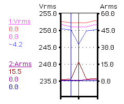
The graph (taken from a very real investigation) shows the points to take and the calculation that needs to be performed. Although not 100% accurate, it is more than adequate for most purposes. This is a screen shot of a graph from a superb piece of DOS software from Telog. It allows the placing of two cursors and to then display the differences in the values between cursors 1 and 2. Note how the changes in Avg and Max of voltage, and Avg and Min of current are 0. This is ideal. In this event the DVmin is 4.2V, and DImax is 15.5 and with R = V/I = 4.2/15.5 this translates into a feed impedance of 0.27W
Feed or Line impedance is not Earth Loop Impedance. A TNC system (including TNC-S) uses a single conductor for both Neutral and Earth up to the meter point and/or beyond. As this conductor is also the Earth reference, Earth Loop Impedance is therefore incorrectly assumed as the Feed or Line Impedance. Earth Loop Impedance is the impedance from Phase to Earth, which encompasses all Earth paths for the current to flow back to the source (with, as in feed impedance, the source being part of this total impedance). As the Earth has more paths to the source than does the Neutral, it is not uncommon to find the Earth Loop Impedance to be slightly lower than the Feed or Line Impedance. However (there is always a catch), with reduced copper in many cables nowadays, the ELFI at an end point in a circuit could be in excess of twice the feed impedance. This value is usually of concern when testing for Earth Faults, and is often referred to as the Earth Fault Loop Impedance (EFLI). This needs to be sufficiently low enough to allow fault currents to operate protection devices (circuit breakers / fuses) within a designated time so as to maintain safety of both life and installation (i.e. limit the rise in temperature of any point in the installation and/or faulty device during the fault).
© 03.03.04 |
 INTERPRETING THE READINGS:
 The best point to calculate the feed impedance is an area on a graph where the voltage appeared relatively constant and a motor start took place. Fridges, freezers, airconditioning units, etc. are good examples and start currents can well exceed 10A. Such a formidable load will create a better voltage fluctuation and minimise the resolution problems of modern digital recorders.