|
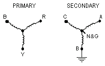
Generally speaking one is likely to find the star point of a VT connected to ground. But there has emerged a system whereby a phase (typically 'B' or 'Centre') is connected to the substation and metering ground. Two stories have emerged from why this is done and it appears there is some truth in both. The first is it takes merely one fuse, this being in the phase to ground connection, to protect all possible shorts to ground, regardless of where on the system. This meant that only one indication circuit was required to indicate that there was a drastic fault within the metering circuits. The second is a more believable one. There are some metering methods that reduce the number of instruments required in order to measure consumption etc. This is often known as the "two watt-meter method", but this indicates the instrumentation method and not why a phase is grounded. The truth is; Such instrumentation is generally 110V but needs to be wired phase-phase for the above meter method. However, a star output VT for this purpose would only generate 63V from the star-point to phase. Most sub-station equipment, as is, also requires 110V to operate and in order to have a proper Neutral (i.e. grounded to Earth) it is necessary to ground one leg of the supply, which happens to be a phase. This would lead to two 110V circuits for use within the substation. Unfortunately, this poses a few problems when trying to measure the voltages from the VT, especially as the star point is no longer Neutral, or even has a relativity to Ground. However, power quality analysers such as the Reliable Power Meters' Power Recorder have a "differential mode input system", meaning the difference in voltage between the respective inputs is what is taken as the input voltages, regardless of their reference to ground. Such an input system allows the user to 'fool' the instrument into believing it is connected to a conventional network, and therefore obtain valuable readings. The first method is to operate in "3-Phase Delta" mode as each phase voltage is measured against the others, regardless of the potentials of the individual voltages with respect to ground. Below is shown a diagram of what would be found with the VT input on the Red-Yellow-Blue (UK colours) incomer, and the inputs to the instrument indicated on the secondary (ignore the N & G connections with 3-phase delta).
Although it is only necesary to connect the N input to the star point to achieve the required results, G is also connected to this point so as to reduce Vn to a negligible figure such that any unsuspecting Power Quality Investigator does not overly concern himself with a high Ground-Neutral voltage. The story changes somewhat when needing to measure the Phase-Earth voltages, otherwise known as the "stress" voltages, on the incoming supply (primary side of the VT).
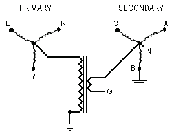
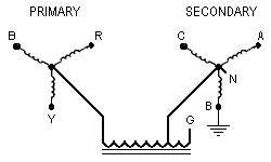
This measurement issue is easily accomplished using a smaller, single phase 'sub-VT'. This allows the "common mode" voltages (as known in the electronics engineering circles) to be recorded. This voltage is representative of the voltage of the whole system with respect to earth.
Also indicated are the connection points for the power quality analyser (A, B, C, N, & G). The Vn channel now indicates the voltage of the incomer star-point with respect to Earth yet the consumption measurement accuracy is maintained. If true stress voltages are not required, or can be calculated from the Vn + Vph (the Reliable Power Meters instrument allows this), then it is strongly suggested that a sub-VT is installed that is capable of handling the highest possible voltage that could be experienced. Should the true stress voltages be required (and errors on consumption readings are accepted) then swap the G and N inputs on the instrument (this only works if the two VTs have the same ratio). Vn still indicates the incomer star-point with respect to earth, but the Va, Vb and Vc readings now show the phases with respect to earth as opposed to usual Phase-Neutral.
© 02.09.01 |
 MEASUREMENT TECHNIQUES:
 If wanting to stay with a star input (for accuracy of reading) we need to convince the unit the reference voltage is 0V when in fact it is not. We overcome the issue by connecting both the G and N inputs to the star point. It is assumed that the Ground-Neutral is no longer of concern as in the method described we are already measuring this through Vb.
 The star point on the VT is often not connected to Ground (which would cure the measurement problem) as this could lead to high ground currents should any imbalance exist on the incomer. The proper method (in power engineering circles) is to use 3 single phase VTs wired as a star-star and to ground the 'primary' star-point. This allows any imbalance to be present but as there is no magnetic coupling between the windings all imbalance currents are eliminated. But what if the VT cannot be changed?
 The preferred type is a fully isolated VT (primary and secondary are seperate) but circuits are shown for both isolated winding and "auto-transformer" style VTs. Please note the phasing of the windings on the isolated VT and the strange connection of the auto-transformer VT.