|
Permissible levels of earth leakage current vary among product types and related standards. The selection of values presented in the table below gives an indication of the range.
Then comes technology, and pales wiring leakage into insignificance! With Live wobbling about at 230VAC leakage amounts to 73µA/nF. Now this may not sound a lot but every item of hi-tech equipment is fitted with some form of filter or protection, or both.
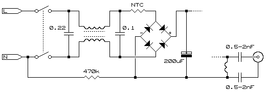
The circuit shown above is the input mains filter as typically found on a standard PC power supply. Before we continue; There appears to be a misconception amongst some engineers about the need for capacitors from each current carrying conductor to Earth. I have even heard it claimed as nothing more than 'bad design' but that "we are stuck with it". In truth, the sadness is in the fact the need for such capacitors is questioned and, even worse, that such incorrect thoughts are taught to others! The capacitors across the L & N (the 0.1µF and 0.22µF) are all very well for differential mode noise, but are useless for any common mode noise (that which exists equal in phase and amplitude relative to Earth on all current carrying conductors). In steps the smaller capacitors from L & N to Earth and are, appropriately, called the "common mode capacitors". Their function is to keep such noise contained within the device (the path of the noise shown in red) and to prohibit it from appearing on the power cable where it can conducted or radiated to other (possibly more sensitive) devices and thereby cause disturbance or malfunction. So you see, this is good design! Believe me, the designers would not use this design if there was no need especially when they are trying to shave every penny off manufacturing costs! But, thankfully, the filters are still there as they serve the additional purpose of keeping noise out of the device too. We cover this later in the section on transients. The input filters of switch-mode power supplies, and other devices using such filters, appear to range from a single stage filter with the lowest value of common mode capacitors at 2.2nF through to the double stage (as shown above) with the maximum value of 4.7nF. This makes the capacitance found in such filters between each current carrying conductor and Earth range between 2 to 10nF (allowing for tolerances). Taking the above, this would make the residual current anything from 0.145mA through to 0.73mA per device. What has also been found is there is no relationship between the power taken and the size of filter capacitors. Sadly, although it would be great if it could happen, there is no way one can come up with a "residual current per watt" figure for IT (or any other) equipment. From experience these common mode capacitors are a minimum of 2.2nF. This makes the total from any one input line to Earth 4.4nF and such a filter will therefore easily "leak" in excess of 300µA at 230VAC. With a possibility of three devices per desk (PC, monitor, and printer) we easily achieve 13.2nF and land up with an average of 1mA per working desk. Now for a scary bit! What is not commonly known is these filters are not necessarily out of circuit when the device is turned off. In the first instance the filter may be built into the power cord receptacle on the equipment. This places it in circuit at all times. At other times the leakage remains through the common practice of putting two rather large (by comparison) capacitors across the switch contacts (to aid spark quenching). This means that, even though the equipment is switched off, there is a solid path (by leakage standards) between the power and the equipment earth. But new technology is not the only blame. Older stuff is too. Even the mains transformer has a fairly hefty capacitance between the primary and secondary as well as the core. This is made even worse with those that have an electrostatic shield between the primary and secondary.
The lower capacitors, as shown in the above circuit, have little or no fundamental current flowing through them with Earth and Neutral tied together. This does not mean they are not doing any work; Their function is just limited to 'shorting out' any Neutral-Earth noise. Just a small recap on the advantages of 3-phase environments; The primary one is that when all voltages are added the result is zero. Similarly, if all currents are equally distributed over the three phases, the result is (hopefully) zero. So in 3-phase environments where the whole load is equally spread across the phases, even though the residual current (if true capacitive leakage) is at 90° to the supply voltage on each phase, the collective leakage of a 3-phase environment should be zero. In reality, the residual current will be higher on some phases than on others; Just the difference in the length of wiring will do this, so expecting a complete null is beyond reality. Also, there are other factors at play in large environments such as common-mode noise and/or zero-phase sequenced harmonics. However, it is not uncommon to find the summed residual current to be lower than the total of the individual leakage of all the loads connected to the supply.
But leakage is not just confined to the work place. Although most homes may boast a PC, almost all will have some form of home entertainment. The worst of these to create leakage is a television set. Below is a diagram of a typical TV mains section.
Also indicated is the antenna connector, and it can be seen that this will (at least it should) eventually find its way to earth through the antenna system. These capacitors will vary in value depending on whether the TV is capable of VHF or UHF, but typically anything between 0.5 and 2nF is not uncommon. The total capacitance would therefore be 1 to 4nF. The problem with the leakage from a TV antenna socket is the waveform on the capacitor is far from a sinewave, which means we cannot apply the typical reactance calculations. Ok, it's not that far from a sine wave, but the fact we are only dealing with half a sinewave means we have an extremely sharp rising edge to contend with, right at the zero crossing! The slope at the zero crossing point of a 50Hz sine wave 444V/S x Vin. For 230VAC this means a rise of 100kV/S resulting in an instantaneous deliverable current of 100µA/nF. On some TVs this could therefore reach up to 0.4mA. Furthermore, this waveform is not a sinewave and the wave shape stimulates nerves more easily. These capacitors are usually rated at a few kV to hopefully stop them from failing during their (or the TV's) lifetime. When they go wrong (and yes, they do), things become interesting! The other aspect of leakage from TV sets is that it only happens on the negative swing of the live, regardless of the polarity of the connection. To make matters worse, all pieces of equipment apparently have the chassis as negative which means there is nothing to compensate. In large residential blocks fed with 3-phase care needs to be taken not to fall into the trap thinking the leakage from the three phases will balance out. Because the leakage is polarized the problem is increased threefold! Added to the high DC component on the Earth system is a new problem of extremely high levels of high order harmonics on it too. While we're here we may as well explain why the 470k resistor is in the circuit in what appears as a strange place. The reason is simple. Ever wonder why they instruct a person to "please switch off before making any connections"? Simple. When the TV is turned off, any voltage present on the chassis of the TV is drained to Neutral via the 470k resistor, and with Neutral being referenced to Earth this would mean the chassis would be rid of any high voltages. Well, this is theory. In practice it has been found that many TVs are wired with L & N reversed, so the resistor simply defeats the object! Ever wondered why the TV antenna socket gives a really good "sting"? Now you know why. But try telling that to some unsuspecting husband whose replacing the antenna cable after it was pulled out while his wife was vacuuming! "Surely it is your electricity that is unsafe!?". "Yes sir, it certainly is!".
© 14.03.04 |
|||||||||||||||||||||||||||
 CAUSES:
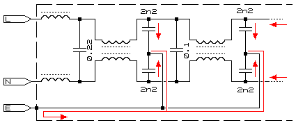
 It's all very well being bombarded about installing lightning protection in an attempt to protect those prized possessions, but MOVs also weigh in at a hefty 5nF per device (which is why most designs are Y constructions - they can use smaller devices which are cheaper, and they reduce leakage by putting the "capacitance" of each device in series).