|
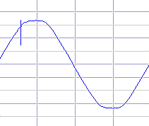
Noise has one description - it is a disturbance to the waveform that generally bears no relationship to the fundamental frequency. This is the noise that resides between Live and Neutral over and above the mains waveform. It would be what would be seen if the fundamental frequency were removed. In electronic terms it would also mean removing the fundamental based waveform, no matter how distorted (i.e. also removing all harmonics). Noise has a number of sources (far too many to mention here except that lightning also falls into this group), and the effect can range from no effect to absolutely devastating. Noise could be singular disturbances such as switching on the network e.g. turning off fluorescent lights in a building or main HV switching by the electricity supplier, through to repetitive disturbances e.g. the switching of inverter thyristors or the non-linear load waveform of a bank of hi-tech devices.
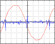
In the first instance the noise could appear anywhere on a cycle, while in the second it would generally occur at defined places on the cycle (in the right-hand example above, the noise is separated out and shown to appear shortly after the zero crossing). Repetitive noise is not always related to the cycle and may be erratic singular disturbances superimposed throughout the cycle with no specific timing. An example of this type of noise is brush motors especially if the commutator has become dirty or unevenly worn, or the brushes are not seating on the commutator properly. In all cases, however, the noise having a high frequency content means it does not make up any harmonic content (although most instruments will indicate it as such). Noise has two methods of manifesting itself, either across Live(s) and Neutral (i.e. such that it combines with or is superimposed on the mains signal), or between Live(s) & Neutral (together) and Earth. These two scenarios are covered separately in the following sections. Before continuing, I need to put to bed one mythical statement first... In some circles, differential mode noise has been given the title of "Normal Mode Noise". This would mean that common mode noise should also have the title "Abnormal Mode Noise"! Once you read the two following sections you'll realize that common mode noise is as normal, if not more normal a mode of noise as is differential mode noise. Quoting a particular noise type as "Normal mode noise" is, therefore, total nonsense! Thankfully, the only time I have seen this terminology being used is when someone is trying to impress a bunch of eager listeners at some or other conference (they don't impress me one little bit!). Those "in-the-know" never use this term. Let's leave it at that! Back to the subject... This is the noise that resides on Live and Neutral and is equal in amplitude but opposite in phase. In split-phase or floating systems, it would be the noise that exists between the two current carrying conductors. As the noise is opposing in phase, there is a natural cancellation and therefore no common-mode component (see below). The level at which Differential Mode Noise becomes an issue is dependent on the sensitivity of the circuitry (usually the power supply) being subjected to this noise. In modern power supplies this would be determined primarily by the characteristics of the mains filter. In older power supplies the transformers act as extremely effective filters as they become high impedance at high frequencies, although care should be taken with regards coupling between windings. It is this last point that may lead some power quality investigators to think that noise on the Neutral is a worse problem that the Live. Depending on which way the winding is wound, the Neutral is either toward the core (inducing noise to Earth) or toward the secondary (and therefore inducing noise to it). Tracing noise is dealt with later. This is the noise that exists, equal in both phase and amplitude relative to Earth, on both the Live & Neutral. But common mode noise has two sources. Either it is noise that exists simultaneously on the Live and Neutral, or it is the Earth reference that moves. It is this latter source that can confuse people because in measurement terms it shows exactly the same result. It is only when the Earth is referenced against another Earth (or Ground) can it be determined whether or not the noise is being introduced through the Live and Neutral, or Earth. Please note we are referring to it as Earth and not Ground, the latter being a direct connection to the Ground through a system connected to (usually dug in) the physical Ground (terra firma). Common mode noise usually doesn't deserve any attention as this seldom has an effect on anything. As long as the Live and Neutral don't influence anything, all should be well. But life isn't like that. The capacitance on the wiring alone could cause the common mode noise to find its way back to Earth, never mind the capacitors found on mains filters adding to the problem. If the equipment is "standalone", then there is usually nothing to be concerned about. It's when the equipment is connected to others that influencing the Earth can have devastating effects, especially if the earthing is weak. The energy may well find its way to other sections of a system via other routes; These routes could be signal cables coupled to sensitive electronic circuit boards rather than the Earth cable of the mains. Although not as destructive, such noise could result in RCDs tripping (except if a PC is being powered through this as it could result in data loss). The common mode noise currents combine within the RCD resulting in nuisance tripping. 'Electronic' RCDs are far more susceptible to this than passive magnetically coupled ones. This is covered in a little more detail in the section on Nuisance Tripping. There is one last noise not commonly known about being "common-mode component" being noise that appears as common-mode noise, and appears in unbalanced systems (i.e. Live and Neutral - and as there is a Neutral it means one conductor is brought to Earth at some point making the relative voltage to Earth effectively nil, discounting the few volts through conductor impedance). Noise is typically conducted through capacitance. If only one current carrying conductor has signal, the only path affecting other items (such as the Earth) is through the one capacitance associated with that one conductor. If only a Live and Neutral were in involved, then it could be drawn as a capacitive divider between Live and Neutral. The common-mode component in unbalanced systems is thus half-V. In a 120V system the common-mode component is 60V. On 240V it is 120V. Should the noise be differential-mode, there is a high possibility of common-mode component of the noise (based on the same rules) e.g. should there be 10V of differential-mode noise, there could be 5V common-mode component of noise. It isn't quite that simple because this rule relies on only one conductor having noise (and signal) and the other not. The true common-mode component is half any unbalance of the current carrying conductors. This is usually added to the true common-mode voltage (i.e. that which exists on all current carrying conductors in equal phase and amplitude) to get to the total common-mode noise to be dealt with. This is the noise that resides between any two points within the system. Transverse-mode noise/signal does not in any way refer to which two points are being referred to, although it is commonly accepted to mean between two current carrying conductors without any reference to Earth. On a 3-phase system this could mean the noise between two Phases or one or more of the Phases and Neutral. As the noise is simply defined as that which exists between two points, it is in no way referring to the noise being truly differential i.e. equal but opposite in phase. Watch out for this definition. It has often been mixed with differential. As there is a high possiblilty of the noise being unequal in amplitude, there is a high possibility of common-mode component. If the noise were to be unequal in amplitude but equal in phase, transverse-mode noise will exist together with a huge common-mode component.
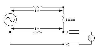
Sorry, there will be those who never read the title, so we will need to repeat it (apologies if you heard it the first time!)... THE NEUTRAL-EARTH VOLTAGE IS NOT COMMON MODE NOISE !! There is this misconception, usually promulgated by some UPS and other such device manufacturers so as to fool unsuspecting customers into purchasing their gear, that such a voltage should not exist. Such a voltage will always exist purely as a result of physics. Wiring has impedance - and that's it! In the picture below, I have shown the wires having impedance and given an example voltage drop (if the wiring is similarly sized) of 1V on each wire.
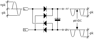
According to the definition: Common mode noise/voltage is the signal that exists on both the Live and Neutral equal in phase and amplitude. In our example above, the signals are undeniably equal in amplitude but they are opposing in phase therefore they cancelled each other out meaning there is no common mode voltage! Measuring N-E, as shown above, will show a voltage of 1V. According to the conventional belief that N-E is common mode voltage, will have those who measure this believe that a common mode problem exists - but we have proved this to not be the case. As the promoters of this teaching can't hide the physics of wire impedance, they set 'levels' that are regarded as 'acceptable'. The ghastly sin is they can get away with this! Until now that is. What I have noticed is that over the last couple of years is the number of articles suddenly (coinciding with after this page of the book was published) doing the rounds explaining the exact same thing (as well as "how it can be used to one's advantage"). For those still not convinced N-E voltage is not a problem... Below is a simplified input portion of a typical SMPS together with an oscilloscope waveforms capture between Earth and the rectified DC.
This waveform shows the 0v of the PSU electronics being 'dragged' to the full negative peak voltage on every negative going half cycle of the input AC. The half-cycle RMS is still exactly the same for the negative going portions thus making the whole cycle RMS half that of the input RMS e.g. 115V on 230V input. Furthermore, there is a rather large capacitor coupling the 0V and +V meaning the same waveform appears on the +V. This makes this waveform common-mode! And, as shown above, a common-mode voltage of 115Vrms exists on the DC portion of the mains side of the power supply electronics. And not only that; There is also nothing 'smooth' about the abrupt start and halt of the half cycle as it leaves and returns to zero! The slope is 100kV/s at 230VAC, but the switching speed of the diodes will be many times that. Imagine what the harmonics 'experts' would say about this! So there you have it! So much for the claims the Neutral-Earth voltage must only be a few volts! And, don't forget about the claims the problem is exacerbated when a few harmonics are floating around too! Not only have I proved, but also substantiated my claim that having a grave concern over the N-E voltage is futile! There is a distinct feeling the entire computer industry has been fed quite a few rather expensive red herrings over the years! But there is one thing to bear in mind. This was at the fundamental frequency and/or low-order harmonics, not the high frequencies of noise. The actual concern is the current that could flow from the current carrying conductors to other parts of the circuitry as a result of noise on the current carrying conductors, regardless of whether it be differential or common mode.
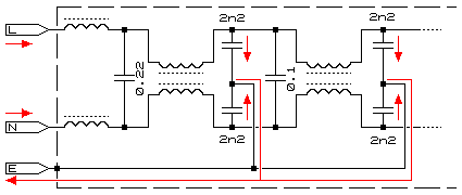
The path is usually not clear. Within equipment the primary path is always towards the equipment earth. The head culprit is the the mains filters; Although their intended purpose is to keep any noise generated within the power supply from getting out, their secondary ability is to keep any external noise from coming in to the power supply, and it does this by transferring any noise on the current carrying conductors to the equipment Earth. And with unbalanced systems both the differential and common mode noise is relevant, the one being half as much a concern as the other. As said previously, the common-mode component of a typical mains supply is half the full voltage, this makes differential mode noise half the concern of common mode noise. To explain this further; In the computer industry there are claims that 10V differential mode noise is the accepted limit. Using the half-voltage rule, this would set the common mode noise equivalent limit at 5V. What is interesting is almost all UPS manufacturers state the N-E voltage limit is a mere 1V i.e. a limit of five times smaller than what it should be. Yip!, another fallacy has been discovered! In their defence; The fact that power is typically delivered in an unbalanced form (Neutral being referenced to Ground) makes measuring true common-mode noise very difficult. The reason is with unbalanced systems the common-mode voltage is half the Live-Neutral voltage. Trying to create a balanced voltage in order to measure the common mode noise generates a result being the Neutral-Earth voltage i.e. back where we started (and what has led many into believing N-E is common-mode voltage). Because of capacitive coupling from the current carrying conductors to Earth, this noise can, and does, affect the Earth; The extent depending on the impedance of the Earth system. This, in turn, affects the Earth-Ground voltage (Ground being terra firma i.e. the external signal cables and Faraday-coupled surroundings of the device connected to the affected Earth). The E-G noise is then what dissipates from Earth through the signal cables etc. to Ground. If one thinks carefully about this, it will be deduced that having a low or non-existent N-E voltage will be of no use should the E itself be wobbling about like a leaf in a hurricane! It is clearly an issue if the earth reference of a device is not maintaining a reasonable similarity to the surroundings, and certainly has nothing to do with how the Neutral into the device is behaving. A further insult to injury is that the N-E voltage may be reduced by the 'shorting out' effect of capacitance between Neutral and Earth (EMC filters, etc.). Such a reduction in level may deem the power supply in an installation "fit for service", meantime the system is crashing with sickening regularity from a grossly affected Earth! Both types of noise (differential and common) are a problem. The only method of truly measuring the combined problem is by measuring the Earth-Ground voltage. This is not easy. But revisiting the statement that it is not voltage that causes damage, but current, means that measuring the current is the more appropriate, and much easier way of determining if any such voltage is an issue. We investigate such measuring methods later.
"Don't know", is the short answer, but, at a conference some 'expert' stood up and was orating forth about permissible voltages on the ground leg of a 48V DC telecoms supply. It was proved, by many, that any noise in excess of 3V would start causing weird things to happen within the gear. Once this voltage reached 5V, equipment damage was said to have been experienced. But hold on! What has just been quoted is the accepted maximum level of noise on the grounding system of a DC supply. What one must not forget is that this ground is also the DC return path, therefore, it is the noise level that is acceptable on the DC supply as a whole. With this in mind then... It is just possible that this level, intended for DC systems, has mistakenly been made the 'acceptable Neutral-Earth voltage' on AC systems, for which it was never intended! Before you scoff, let's consider one thing. If one were to accidentally swap Neutral and Live at a piece of equipment, this would make the Neutral-Earth voltage 230VAC/50Hz. This is equivalent to 2.3V at 5kHz, noise-wise, and is a whopping 11.5V at 1kHz when based on typical passive filter responses of 6dB/octave. But the equipment didn't care... and we land up with more food for thought! When levels are quoted, it needs to be questioned if both the equipment and its environment is taken into account as the susceptibility of a device to noise is not only governed by the device, but its environment too. In one situation a device may malfunction with only a low level of noise, but in another the device is totally unaffected by even high noise levels. Let's explain... There is one aspect of noise that is not very well understood, especially by know-it-all IT folk. Noise, being high frequencies, can couple both inductively and capacitively from one piece of wiring to another. If just taking capacitive, a 100pF capacitance (two cables lying next to each other for 1 metre) will allow more than 1mA leakage at 200kHz. This may appear like a high frequency, but the sharp edges of noise spikes easily attain this. In many instances noise spikes, and this includes transients, can have very destructive influences on an installation (even if only as software crashes) but through no fault of the equipment. The equipment designer can only do so much. He cannot control the fool who wires it up! The reason noise is such an issue is there are two means by which the noise finds its way around. The first is conducted down wires, the second is radiation. When conducted down wires the noise can make its way into a piece of sensitive equipment via those same wires. The equipment may not necessarily be damaged, but may well malfunction through being disturbed. Once radiated, noise cannot be stopped! Yes, it will diminish rather quickly, but it has effectively escaped and is happy to be absorbed by any piece of wire willing to do so. If this is a sensitive telecoms circuit, well, disturbed it shall be. What has been indicated in the previous paragraphs is the extent to which noise will cause an issue is dependent on the level of noise versus the sensitivity of the device to the said noise versus the environment of the device i.e. how subjected the device is to the noise. In some instances the noise may be many hundreds of volts before it causes even a single hiccup in a piece of hi-tech equipment. In other circumstances not even a volt of noise could cause problems. One cannot set levels; Only deal with cause and effect. Finally; A critical issue regarding noise is that any causing radiation above 150kHz could affect some forms of aircraft navigation, and it is therefore of paramount importance to ensure that such radiation is firmly kept under control (hopefully the designers of very fast switching power electronics bear this in mind).
© 03.05.03 / 12.05.05 |
 Causes:-