|
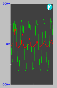
When introducing the characteristics of inductors, I will invariably refer to them as "frequency dependent resistors" where the higher the frequency, the higher their "resistance" - which, I know, should be referred to as "impedance" and even more correctly "reactance" - but go with me on this one for a moment. It is this last term, reactance, that has led me to characterise them as frequency dependent resistors because this is exactly how they react i.e. the higher the frequency for a given voltage, the lower the current through them. As seen on the previous page, the waveform of the supplied voltage is now most likely to be modified away from a pure sinewave (even if it is not your own load that is doing this modification!). This modification is introducing high-frequency components to the voltage applied to the inductor. Back to our resistor for just a moment; A resistor's linear characteristic was defined by the fact the current curve of a resistor accurately follows the voltage curve, regardless of the shape of the voltage curve. Inductors, with their "resistance" being frequency dependent, are naturally reluctant to conduct higher frequency components, and the higher the frequency, the more reluctant they will be. Because of this, inductors will have a tendency to retain their sinewave load characteristic even though the curve of the applied voltage is not. So, in an imperfect world where the applied voltage is not a pure sinewave and the current curve is not replicating the voltage curve (even if one ignores the phase angle), the inductor can not be referred to as a linear load. If it were, the harmonic content of the current would be equal to the voltage, but the two captures below show it to be less on the higher harmonics. insert harmonic captures here Although their current curve is more sinusoidal than the voltage, inductors are not linear loads! I know, this will come as a shock to a lot of folk!
There is one aspect of distortion often overlooked being unequal distortion between the two half cycles. If the RMS value of the two half-cycles is unequal then a DC component forms on the network. This can be masked in some AC monitoring devices if AC coupled or fitted with relatively short timing on offset compensation circuits.
The main problem is it can lead to transformer magnetic biasing which can cause the transformer to "collapse", this seen in the accompanying screenshot. The next problem is any direct rectified device (such as a switch mode power supply). Most of the current used by the device will be supplied through the diodes that conduct on the half cycle with the higher absolute peak voltage. Another area of concern is the the two zero crossings are not equally spaced with the shorter timing existing towards the weaker half-cycle. Such unequally spaced crossings can affect phase locked loop devices such as uninterrupted power supplies that look at both crossings in an attempt to capture mains failures more quickly. This problem can extend into any devices that use the mains cycles for timing. Inductors Introduced Capacitors >>
© 15.10.04 |
 CAUSES:
 Having a DC component on the current usually doesn't affect much as long as one remains below the hysteresis level of the transformer (see below), although it can cause breaker trips if such breakers are sensitive to this. DC biasing on the voltage, however, has some serious effect on almost all pieces of equipment.