|
It is possible for certain power quality issues to be related to the type of connection to the network. It is highly possible for noise to be introduced into an I-T installation from a user on the same source, especially if using a TNC-S system. From the introduction to this section it can be seen, as with many fields of engineering, there are terms and abbreviations for various methods of doing things. We hope to remove the confusion here. However, before we start, such abbreviations are dangerous and could be proven to contravene almost every safety regulation in the book! Please use them sparingly, and at any sign of there being any confusion then please switch to the English equivalent i.e. say what it is in words! There are a few letters used to describe the following types of network connection and we cover them first. The notation system is simple. Firstly a hyphen is used to state where the system changes from one type to another, and this usually means the metering point (the point at which responsibility for the distribution transfers from supplier to user). Ahead of the hyphen (if used) is the source, after is the load side of the connection. Apart from Z, all the letters are pretty well known in industry. The use of Z is mine and one I am hoping industry will adopt as a viable alternative to I. The reason is I is used for either Isolated or Impedance earth arrangement and could lead to confusion. Using Z removes this and clearly states whether the system is isolated or has some intended connection to terra firma. The following are standard configurations found, but these are by no means the only configurations seen. Knowing the supply configuration may well assist in finding the reason behind a power quality issue or, better still, knowing what was specified and why the "as built" is causing trouble! In all of the following diagrams, the dashed line represents the Point of Common Coupling (PCC) i.e. the point at which the source or feed enters the premises (where the responsibility changes from Supplier to User).
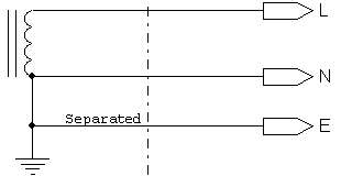
Ground supplied at source and Neutral and Protective Earth supplied to user separately.
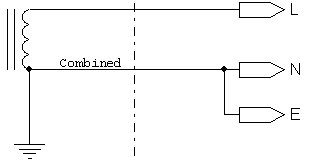
Ground supplied at source and Protective Earth & Neutral combined (usually on a single conductor, referred to as PEN) all the way to the used point. This type of connection is very uncommon.
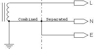
Ground supplied at source and Protective Earth & Neutral combined (usually on a single conductor, referred to as the PEN) to metering point and then split and supplied to user separately. This is also referred to as a 'PME' (Protective Multiple Earth) supply. To complicate matters, this type of connection is often referred to as a 'CNE' (Combined Neutral Earth) supply but is intended, when used, to indicate a special concentric cable connects the supply to the user. The 'CNE' cable looks much like a coax cable consisting of an inner conductor which is used for the Live, and an outer conductor (usually made from single strands wound around the inner) used for the combined N + E.
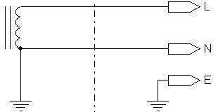
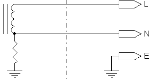
Ground supplied at source for Source Earth and Neutral, but User's Protective Earth supplied by User.
Ground supplied via impedance at source for Source Neutral (usually done to limit Earth Fault currents), and User's Protective Earth supplied by User. Please note that the designation Z-T is still not wholly adopted in industry which still refers to this as an 'I-T' (Impedance-Terra) supply - please see next for reasons this is dangerous.
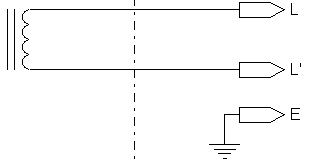
Source is isolated, and User's Protective Earth supplied by User. Please note that this designation is still erroneously used in industry indicating 'impedance grounded' - please see previous designation for reasons this is dangerous. Also note the lower leg is no longer referred to as Neutral, but rather as L' (Live Complement). There are two reasons for this. The first is this leg is no longer 'neutralized' to the surroundings i.e. Earth, which, by the way, is where Neutral got its name from. The second is a voltage is likely to now develop on L' because of the natural capacitance (with respect to Earth) found on both legs of the supply attempting to balance the supply about Earth i.e. in a 230V supply, L and L' will each be 115V AC with respect to Earth. Advantages are all voltages with respect to Earth are kept as low as possible and also allows an Earth Fault to develop without causing a trip. However, during such a fault, the opposing leg will now reach full working voltage with respect to Earth and therefore such systems must always have Earth Fault Warning Devices. If it is imperative for a trip to occur on an earth fault, yet the advantage of reduced voltages with respect to Earth are required, then look at the 'RV' system below. Note: Do not be tempted to refer to this as an 'IT' supply (no hyphen) as this could be confused with Information Technology supply, something that may well exist in a premises e.g. an I-T supply feeding an IT system (especially as this, because of the advantages of not tripping with an earth fault, is being adopted in many data centres!).
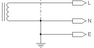
Not one heard of very often, unless you deal with audio equipment! The Neutral is deliberately brought to Earth at the user so as to ensure the whole supply is as noise free (relative to the Earth) as possible, and earth loops are minimised if not eliminated. This is normally accomplished by the user ordering an I-T supply and then bonding the Neutral to the Earth at the entrance point, normally on a Main Earth Terminal. Star Earthing (including Cascaded Star Earthing) is then used throughout the site so as to eliminate earth loops. In many instances this cannot be achieved and the user has to resort to installing a Delta-Star isolation transformer (this ensures there is no need or reason to connect the incoming supply to the users local Earth thus keeping it noise free) and the user then creating a TNS supply from the transformer output.
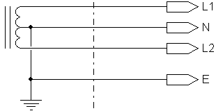
"Reduced Voltage" or "Reduced Low Voltage", also referred to as "Split Single Phase". This is not part of the normal designation, but one I wanted to throw in anyway as this is both the normal method of supplying domestic properties in the US (yes, the US has been running 230V for years!), and in areas where, for safety, the maximum voltage with respect to Earth needs to be kept as low as possible. It has the advantage of an 'I-T' supply as the voltages are kept as low as possible with respect to Earth, but with the added advantage of a trip will occur when an Earth Fault develops. In truth, the above is a TNS supply with a very approved of twist! (I wish we could adopt this here!). There are two areas of concern with regards this type of supply, especially in light of the new BS7671 colours. L1 and L2 could be confused as being two phases of a 3-phase system (as the new regs say one may use a single colour and call the phases L1, L2, & L3). It may prove prudent to refer to the two Lives as L & L' (Live Complement). The second is colours. Most boards I have worked on (in South Africa and the UK) have used Red and Blue (not black, this being the older Neutral colour and therefore, as voltage is present, is not technically correct). This could again lead someone to believe this is two phases of a 3-phase supply. Admittedly, confusion was kept to a minimum as the RV board was completely separate to a genuine 3-phase board. RV is usually designated to 115-0-115 (230V total) systems, and RLV to 55-0-55 (110V total).
© 30.05.04 |
 CAUSES: