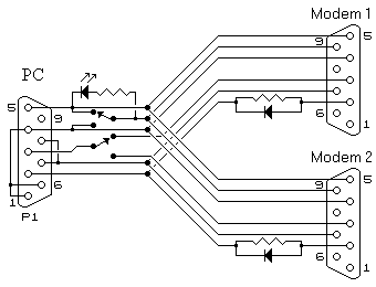
Elpro 405U Radio modems often require testing as pairs. Although the bit error rate could be used as a test for radio integrity humans are more easily satisfied when seeing data sent and received as would happen in a live situation. This would usually be accomplished using 2 PCs with the first sending data to the second via the modems, however, this is not always practical and results in equipment having to be arranged and coupled up every time such a test is to be performed. With the following cable such tests can be carried out using only one PC making the tests easier to carry out.
The principal of operation is the modems are either in local command mode or modem mode therefor the data being sent to the selected modem is either being responded to (according to the configuration) or transmitted by radio to the recipient modem with the data then appearing on the port of the second modem. It is known that two RS232 ports cannot be connected to each other but with the use of simple signal diodes and resistors, as shown above, two ports can be connected to each other such that data appearing at either port will be received by the PC. Should both ports transmit simultaneously the data will be corrupted but without damage to any of the ports. Using a suitable terminal software program (e.g. Hyperterm - if you must!) data can be sent, transmitted, received, and passed back to the PC. Whatever is typed should be seen on the screen (almost immediately if transparent mode is used). Using the sequence '+++' to force the modem into command mode will allow direct comms to the modem for set-up purposes without having to reconnect a single plug. The lower switch allows for easy selecting which modem is to transmit / be set-up. The upper switch selects "Radio Program" mode, the LED indicating when this mode is selected. Only synthesized radios can be programmed to different frequencies and you will require the correct configuration program in order to achieve this. Please exercise extreme caution when programming the radio. Resistors are 10 kilo-ohms If there are any questions please email © 14.08.00 |
