|
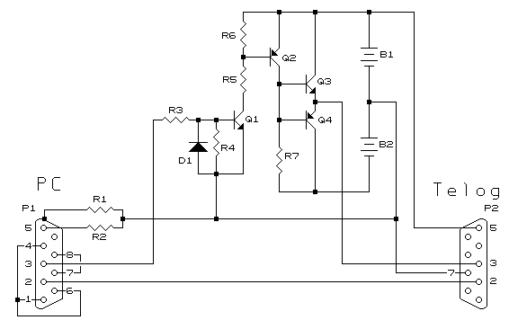
The circuit described is for use between a notebook PC and a Telog Linecorder when the notebook has, or is suspected of having, weak drive on the signal lines. Circuit Description The Tx signal is fed via R3 to the base of Q1. When in the 'mark' (rest) state D1 ensures the base of Q1 is not forced negative so as to start conduction. When the signal moves to the 'space' state Q1 conducts. This is turn forces Q2 on. This raises the bases of the output complimentary pair. The emitters, following the bases, pull the output high to the 'space' state. When the input returns to the 'mark' state Q1 turns off, turning Q2 off, and R7 pulls the bases of the output pair negative, the output pair thus pulling the output to the 'mark' state. Pin 5 is supplied from B1 so as to not drain the Tx pin of the PC port.
This circuit has one other feature in that no switch is required as when both ends are unplugged the circuit draws no current except leakage through the transistors (which is kept at a minimum by R4 and R6) which is less than the self discharge of the batteries! Parts List R1, R2 - 10 to 22ohms D1 - 1N4148 Q1 - BC337-25 B1 - 9v PP3 If there are any questions please email NOTE: This webpage does not form part of any official documentation. |
© M.T.P. - 30.03.01 |
