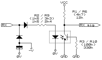
Linecorders are intended for operation on fully compliant RS232 Com ports. Lately comms with some newer laptops has been known to be unreliable with the ports complying to the less power hungry EIA-562 spec. The Linecorder's optically isolated comms port was not designed to operate with the typical ±5V output swing (as opposed to ±12V of RS232). By changing a few resistors, the sensitivity of the Linecorder port can be reduced from the typical 6-7V volts down to 2.5-3V which complies with both RS232 and EIA-562 minimum signal receive capability requirements (yes, I know, this opens a can of worms about whether or not they were RS232 compliant in the first place, but let's not go down that route!). Only two models are discussed here being those that are available on the European market (CE approved). These are the single phase LC-812 and 3-phase LC-836i. Other models may have similar port circuits and with a little detective work the appropriate resistors can be located and changed.
The diagram shows the modified port. The designation is 812 / 836, the original values in parentheses, the new values shown last. The collector resistor is increased to 12K. This automatically reduces the current required on the input (owing to the transfer ratio of the opto-coupler). The base resistor was increased to 330k. This results in no current through the collector resistor at 2.5 volts input and the opto-coupler fully saturated with an input of 3V. If one accepts the RS232 standard being an input swing of ±12V and the maximum current to be drawn of 4mA then we can also reduce the input current limiting resistor to 2.4K (836i only). This is based on 12V input less the opto-coupler drop (1V) and the diode drop (0.6V) leaving us with 10.4V. When divided by 4mA this equals 2.6k (2.4 being the next best thing). The result will be a slightly higher current on the input at worst case being 3V. The result is 3 - 1 - 0.8 = 1.2 / 2.4 = 0.5mA (every little bit helps). Note: Some 812s have been fitted with a 3k3 input resistor (R2). If this is the case then reduce this to 2k4 as per the 836 mod. The 812 is relatively easily modified with the top board simply removed. The 836 is best modified with the soldering done from the component side although it is recommended such work only be carried out by experienced repair personel. NOTE: Remove the battery during modification. As the unit will lose the battery backup, ensure all required data is downloaded before work is started and program the unit when work is completed. If there are any questions please email NOTE: This web page does not form part of any official documentation.Any information contained herein is used at own risk. © M.T.P. - 11.05.03 |
