|
In the document "Monitoring Across UPSs", we introduced a method for using current probe channels as voltage channels. However, this method was only valid for Power Recorders and current probe versions of the MultiPoints. However, not to be deterred by such a simple fact, there is a very acceptable method of converting voltage to current using a bit of lateral thinking, innovation, and common sense. In both of the following solutions, transformers are used to produce a low voltage that is then fed through a resistor to create a current proportional to the input voltage - and therefore read voltages using the current channels. This solution involves using 'working voltage input, low voltage output' isolation transformers (e.g. 230V:6V bell transformers - these have excellent isolation properties as they are built for unearthed domestic applications where safety is of prime concern). The output is fed through a suitable resistor and 1W per volt output is recommended i.e. 1A at full voltage. A higher current will result in extreme heat loss with no benefit (and a possibility of the transformer burning out!). Do ensure the transformer is capable of delivering this current continuously. Please do not be tempted to use a lamp as the resistor. These have "constant current" characteristics and will not accurately reflect input voltage fluctuations.
A single turn secondary is created using a piece of copper tape passed between the bobbin and the iron core (if tape is not available then wire, just thin enough to pass through the gap, can be used). The single turn is then immediately fixed to a reasonably thick wire so as to not lose too much of the voltage created by this single turn. This is then taken to the current input of the MultiPoint or InSite. This method is exactly the same as the previous method except that the wire between the transformer and current input now forms the resistor. Transformers have a "turns per volt" ratio meaning that for each turn only a fraction of a volt is created. This means that in order to achieve the recommended 1A representing working voltage, the resistance needs to be a fraction of an ohm - wire is such a resistance. The only requirement now is to measure the input of the transformer using a good multimeter, the current read by the MultiPoint or InSite, and to then adjust the multiplier such that 1A = 1V (for simplicity). Please note the wires running between the transformer and current input must be twisted or in a cable. This is necessary to keep the two in close proximity so as to stop inductive effects. Also, please ensure the wire is at least two metres in length else the current into the system may be excessive. If the current is still too high, the length can be increased to introduce more resistance therefore reducing the current. Recalibration will be needed after this. If there are any questions please ask. Note: This web page does not form part of any official documentation. © M.T.P. - 12.12.02 |
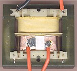 In this solution we create a very low voltage output from a standard "frame type" transformer. In this case nothing is prohibiting the use of an already installed transformer such as a 24V control system supply. As long as the transformer is coupled to the voltage needing to be measured, and is capable of working at the voltage in question, and has a small gap between the bobbin and the iron core, you're in business!